

Description
About the Circuit:
IC1 as shown in the circuit diagram is wired as an astable multivibrator. When the voltage at trigger input pin2 of IC1 is below 1/3Vcc, output at pin3 changes its state from low to high. This is achieved by putting the probe on strip, which changes the voltage level of pin2 below 1/3Vcc and IC gets triggered.
The IC generates note according to the timing components designed using capacitor C1, resistor R1 and combination of resistors R2 to R16 which are selected using probe.
At a particular instance, the combination of R1 and R2 to R16 charges capacitor C3, and voltage across the capacitor keeps on increasing. When it becomes 6V, the threshold voltage at pin6 makes output at pin3 low. Now C3 starts discharging through R2 to R16. As soon as voltage of C3 goes below 1/3Vcc, pin2 sense this voltage and switches output at pin3 from low to high. In this way, we get the square output at pin3 since C3 charges and discharges through R2 to R16. The charge and discharge times can be varied by changing values of combination of resistors from R2 to R16 through probe which in turn change the charging and discharging periods of C3. Thus the frequency of oscillation is changed and in turn note is changed.
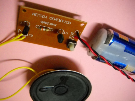
For a sweet melody sound it is required to have a symmetrical square wave. Thus R1 should be kept small as compared to R2 to R16. For making the keyboard, PCB with copper parallel strips on it are readily available.
Resistors of 5% tolerance only should be used. A resistance with 10% tolerance can change the note considerably.
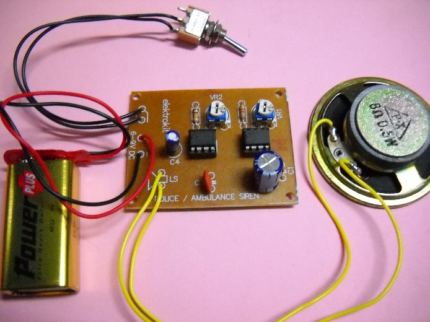
The circuit uses 9V DC supply, so a battery of 9V should be used for satisfactory operation.
Reviews
There are no reviews yet.