


Description
About the Circuit:
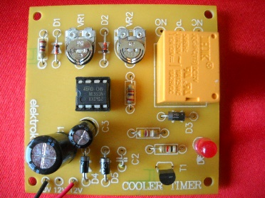
IC1 has on-chip oscillator whose frequency is determined by external RC network connected to pins 9,10 and 11. When power is on, pulse at junction R4-C2 resets the counter and counting starts. The output at pin3 of IC1 is low, which is given to inverter input pin3 of IC2. This low voltage input becomes high at the output of inverter at pin2. Transistor T1 turns on and relay gets energised. T1 remains on until output at pin3 of IC1 becomes high.
When the counting reaches to last bit or the time is over, output at pin3 of IC1 becomes high. As a result the pulse at pin2 of IC2 goes low and T1 turns off. At the same time relay becomes off and it remains off until pin3 of IC1 goes low again.
Here LED D1 and D2 are used to give visual indication. D1 gives the indication of timing pulse generation, whereas glowing of D2 indicates timer on indication.
Reviews
There are no reviews yet.